Categories
AI/ML IoT

How I Built a Connected Artificial Nose (and How You Can Too!)

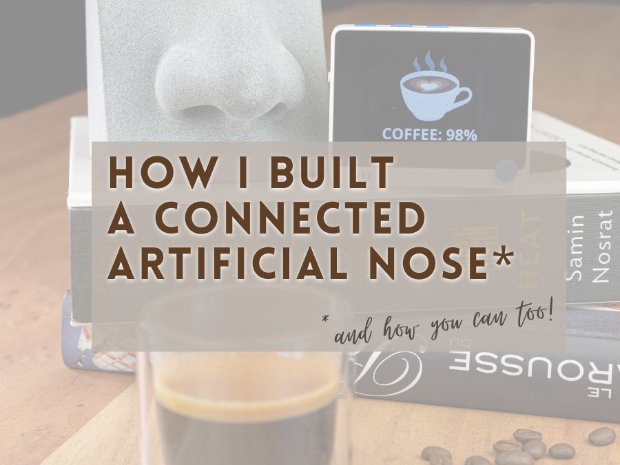
Over the past few months, I have worked on a pretty cool project that some of you might have already heard about as it sort of went viral. I built a DIY, general-purpose, artificial nose that can smell virtually anything you teach it to recognize!

The artificial nose in action, smelling coffee ☕ and whiskey 🥃.
SeeedStudio’s Multichannel Gas Sensor v2.

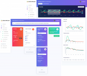
It is powered by the Wio Terminal (an Arduino-compatible prototyping platform), a super affordable electronic gas sensor, and a TinyML neural network that I trained using the free online tool Edge Impulse.

Cover of Make: Magazine Vol. 77.

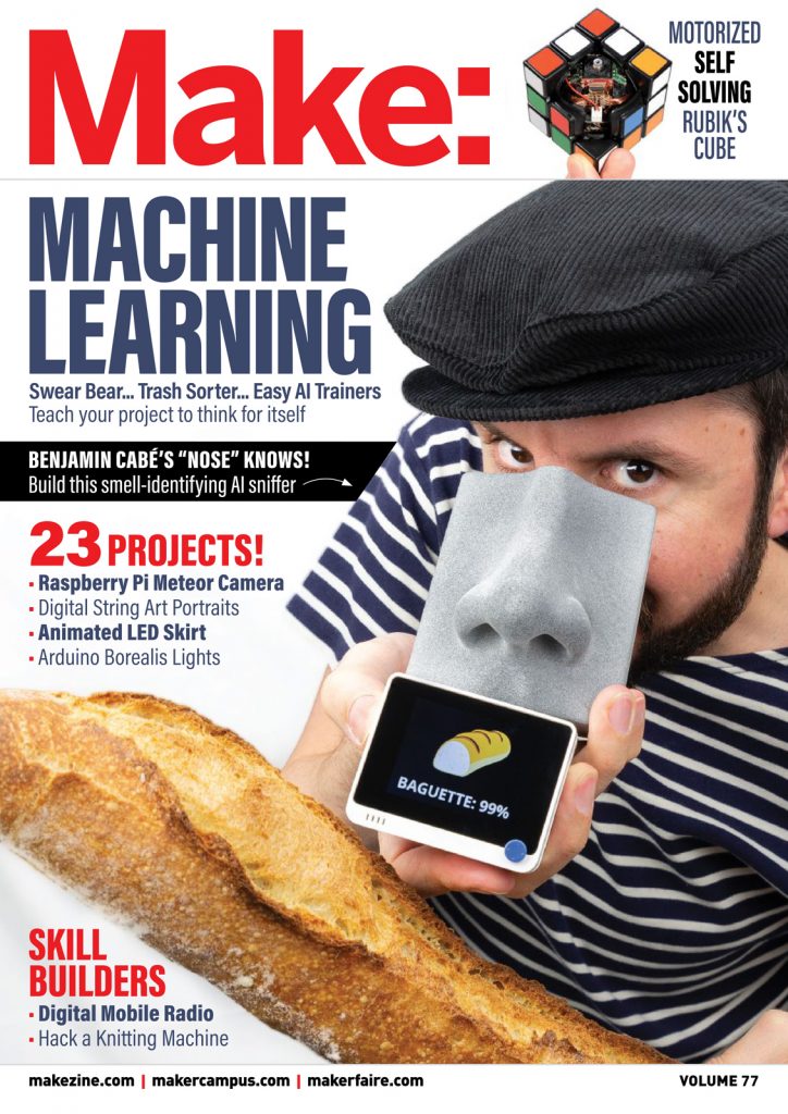
The project was recently featured on the cover of Make: Magazine, and I encourage you to check out the article I wrote for them before reading further.

The Make: Magazine article covers a lot about how you can build the artificial nose for yourself, so I want to use this blog post to dive deeper into why this project is so important to me. In particular, I want to share with you how it helped me understand more about AI than I’d ever thought, and how I eventually ended up connecting the “nose” to an IoT platform (namely, Azure IoT).

[toc heading_levels=”1,2,3″]

Making Neural Networks Tangible

Despite being passionate about all things software, Machine Learning (ML) has always been a field that’s eluded me, perhaps because it tends to be too abstract and too much maths for my visual brain?

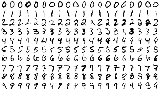
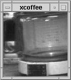
Sample images from the MNIST test dataset.

Speaking of visual things, every time I have tried to open a book promising to be an introduction to ML, most of the introductory examples involved image classification (ex. automatically recognizing handwritten digits from the MNIST database). And, sadly, those innocent pixels would be anything but visual to me, as they would quickly turn into abstract matrices.

So when I started to think of implementing an artificial nose, I didn’t initially approach it as a Machine Learning problem. Instead, I tried to use my intuition: “What characterizes a smell?”. And my intuition was telling me that somehow I needed to establish a correlation between the concentration of the various gasses measured by the gas sensor (carbon monoxide, ethyl alcohol, etc.), and the associated smell. However, doing a simple read of the gasses concentration at a given point in time would probably not cut it: how would it make the difference between a really strong alcohol smell, and one that was maybe more volatile?

Quickly, I realized that acquiring a couple seconds of sensor data would probably be just enough to “capture” the olfactory fingerprint of each smell. With these few seconds of sensor data, I could look at the variation (min, max, average, etc.) of the concentration of each gas, and this would hopefully characterize each smell.

It turns out that once I had extracted those characteristics—something that I can now refer to as feature extraction, like the AI grown-ups, and which was really easy to do using the Edge Impulse tool suite—all that was left was to effectively establish the correlation between them and the expected smells. However, I didn’t really know what kind of neural network architecture I would need, let alone what a neural network was anyway. So, once again, I leveraged the Edge Impulse environment.

It turns out the kind of classification problem I was looking at was reasonably simple: given the minimum/maximum/average/… concentration of each gas on a given time period (I found 1.5s to be the sweet spot), what is the predicted smell? And one simple way to “solve” that equation, is to use a so-called fully-connected neural network, like you see below.

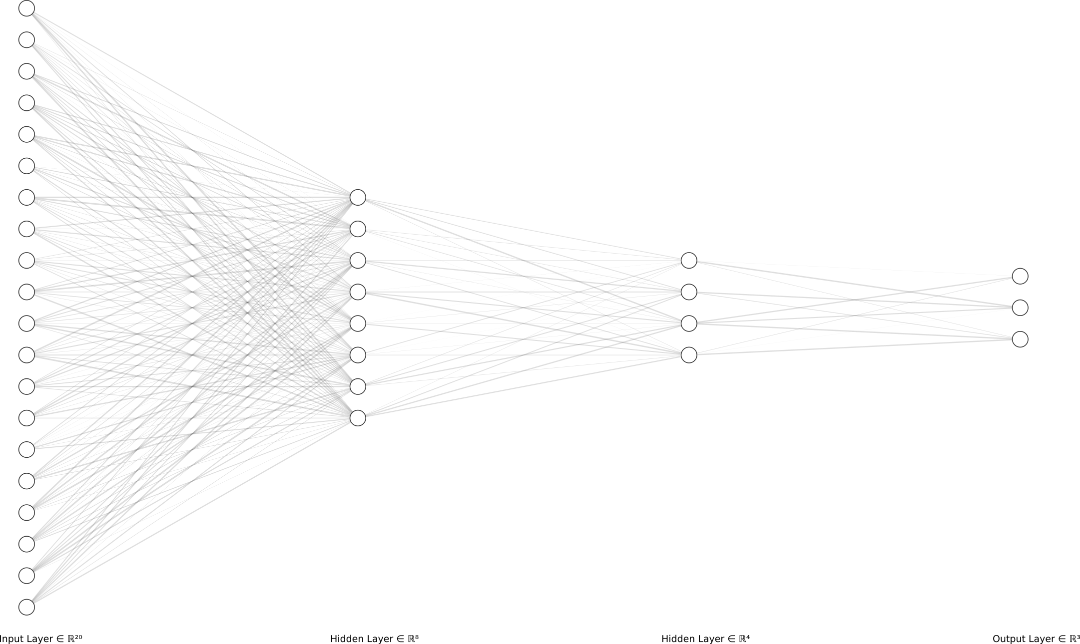
During the training phase, the training data represents the ground truth (ex. “This is 100% coffee!”) and is used to tweak the parameters of the equation—the weights of the neurons—based on how much each characteristic (ex. the average concentration of NO2) accrues to each smell.

Once the model has been trained, and during the inference phase, a given input/olfactory fingerprint entering the network (left-hand side of the diagram), ends up being “routed” to the appropriate output bucket (right-hand side). effectively giving a prediction about what smell it corresponds to.

Building an actual nose

When I initially shared my project on social media back in May last year, I quickly realized lots of people were interested in it.

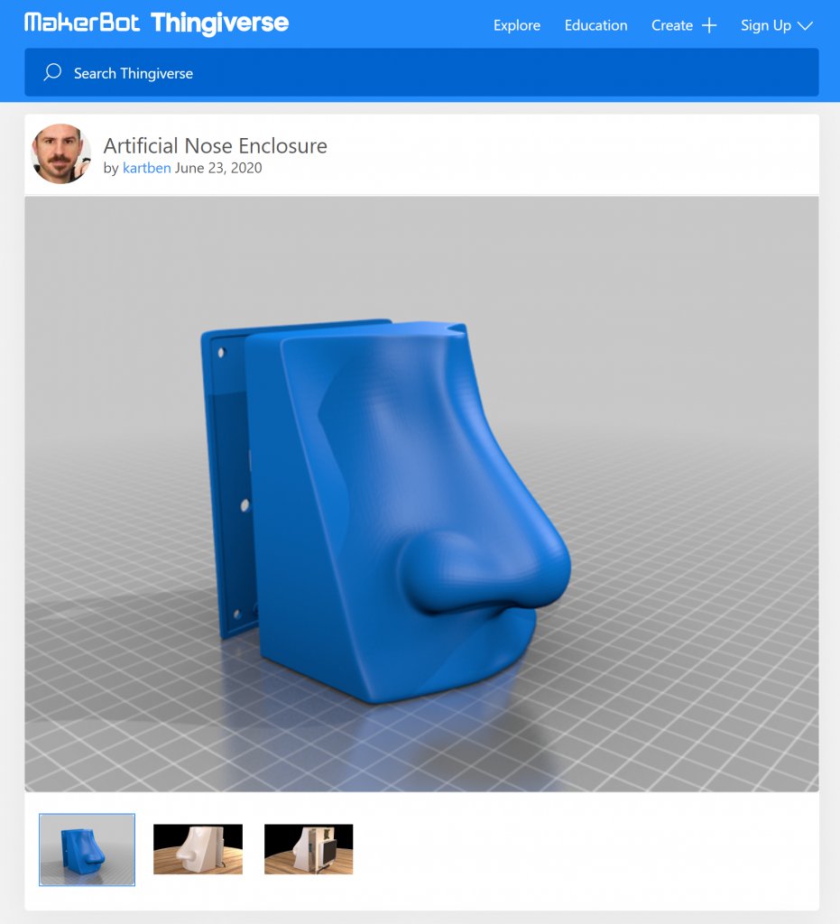
This motivated me to go further and to turn my initial prototype into an actual nose! I had never done that before, so I ended up teaching myself how to use 3D CAD software so that I could design an actual enclosure for my device. I picked Blender—which I would not recommend for pure CAD stuff as there are better alternatives out there, ex. TinkerCAD—, and 3D-printed the resulting plastic enclosure.

A screen capture from the thingiverse.com website titled "Artificial Nose Enclosure" that show a blue 3D rendering of a nose.
The Nose Enclosure on Thingiverse.

Turning the nose into an IoT device

An interesting aspect of TinyML is that it enables scenarios where your low-power, constrained, microcontroller-based equipment is completely autonomous when it comes to performing machine learning inference (ex. guessing a smell). It is very powerful, as it means your sensor data never has to leave your device and you don’t need to rely on any sort of cloud-based AI service. But on the other hand, it also means that your smart device might not be so smart if it ends up living in its own echo chamber, right?

At the heart of an IoT solution is often the “thing” itself, and it makes a lot of sense to design it to be as smart as possible for there are many reasons why relying on any form of network communication or cloud-based processing is at best impractical, sometimes plain impossible.

Connecting the Artificial Nose to Azure IoT Central

The Artificial Nose is effectively an IoT Plug and Play device.

As soon I was happy with how it performed at smelling things, and once I had completed the development of the graphical user interface, I did use the Azure IoT SDK (and some of the work I had done last year) to enable the nose to talk to the Azure IoT services.

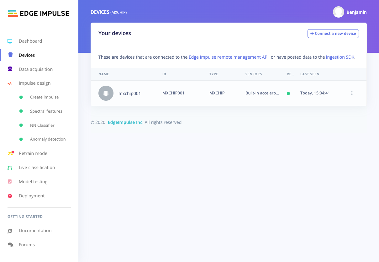
It means you can very easily connect the device to Azure IoT Central (using the Wio Terminal’s Wi-Fi module), and get access to gas sensor data telemetry in near-realtime, see what the device is smelling, etc.

More importantly, you can automatically trigger rules when, for example, a bad smell is being detected, therefore allowing the nose to be much smarter than if it were just a standalone, offline, device.

Connecting the Artificial Nose to Azure IoT Central – Real-time telemetry.

If you built the artificial nose for yourself—and I hope many of you will consider doing so!—here are the simple steps for you to connect it to Azure IoT Central:

  • First, make sure that your Wio Terminal is running an up-to-date WiFi firmware by following these instructions ;
  • Create a new Azure IoT Central application (if you already have one you want to use, that works too!) ;
    • In the Administration section of the IoT Central application, look for the Device Connection menu.
    • Open the SAS-IoT-Devices enrollment group and take note of the following credentials that you will need to connect your AI nose(s):
      • ID Scope
      • SAS Primary Key
  • Flash the Wio Terminal with the latest Artificial Nose firmware (or deploy your own custom build) ;
  • While the Wio Terminal is powered, keep the three buttons (A, B, C) at the top pressed, and slide the reset button. The device should now be showing a black screen ;
  • Connect to the Wio Terminal over serial and check that it’s running the configuration prompt by typing help, which should show you the list of supported commands. Type the following commands to configure the WiFi connection and the Azure IoT credentials
    • set_wifissid <your_wifi_ssid>
    • set_wifipwd <your_wifi_password>
    • set_az_iotc <id_scope> <sas_primary_key> <device_id> (id_scope and sas_primary_key as per earlier, and device_id being the ID you want to give your device in Azure IoT Central)
  • Reset the Wio Terminal, and voila! You should now see a new device popping up in the Devices section of your IoT Central application.

Digital Twins meet virtual senses

Like I mentioned above, having the nose talking to an IoT platform enables scenarios where e.g. you trigger an alert when a bad smell is being picked up. But what is a bad smell anyway? This might depend on a lot of different factors, just like the final destination for the actual alert might be highly dynamic.

Let me try to illustrate this with an example of a real estate cleaning company in charge of buildings all around the city of Chicago. Their information system already allows them to keep track of their personnel and associated cleaning schedules, but in a pretty static way: cleaning people are going to their assigned location once a day, no matter what. From time to time, it turns out that the location doesn’t really require urgent cleaning (hello, COVID-19 and slow office spaces!), in which case the cleaning staff would have been better off going to a place that actually required servicing.

Beyond the apparent buzzword, the concept of Digital Twins consists in nothing more than augmenting the information system (staff directory, building inventory, cleaning schedules, etc.) and overall knowledge graph of the cleaning company with entities that correspond to physical, connected, assets.

With that in mind, a mere “it doesn’t smell so good in here” signal sent by a sniffing device sitting in an office building can immediately be contextualized, and appropriate actions can be taken. Based on where the device is effectively located, it becomes easy to figure out who is the person responsible for cleaning that space on that particular day, and to notify them accordingly.

Connecting the Artificial Nose to a Digital Twins environment.

Get started today!

Many people have already started to build the device for themselves and to experiment what adding “virtual smell” to their devices and applications could mean. If this blog post inspired you to join them, I will leave you with the only two links that you really need to get started:

TinyML powered Artificial Nose Project kit with Wio Terminal
Dark Mode

artificial-nose (this link opens in a new window) by kartben (this link opens in a new window)

Instructions, source code, and misc. resources needed for building a Tiny ML-powered artificial nose.

If you enjoyed this article, don’t forget to subscribe to this blog to be notified of upcoming publications! And of course, you can also always find me on Twitter and Mastodon.

Categories
AI/ML IoT

How to run TensorFlow Lite on the MXChip AZ3166 IoT Devkit

This post will be a short one in my ongoing series about TinyML and IoT (check out my previous post and video demo here).

In a nutshell, you will learn how to run the TensorFlow Lite “Hello World” sample on an MXChip IoT developer kit. You can jump directly to the end of the post for a video tutorial.

You may have not realized, but unless you are looking at real-time object tracking, complex image processing (think CSI crazy image resolution enhancement, which turns out to be more real than you may have initially thought!), there is a lot that can be accomplished with fairly small neural networks, and therefore reasonable amounts of memory and compute power. Does this mean you can run neural networks on tiny microcontrollers? I certainly hope so since this is the whole point of this series!

TensorFlow on microcontrollers?

TensorFlow Lite is an open-source deep learning framework that enables on-device inference on a wide range of equipment, from mobile phones to the kind of microcontrollers that may be found in IoT solutions. It is, as the name suggests, a lightweight version of TensorFlow.

When TensorFlow typically positions itself has a rich framework for creating, training, and running potentially very complex neural networks, TensorFlow Lite only focuses on inference. It aims at providing low latency, and small model/executable size, making it an ideal candidate for constrained devices.

In fact, there is even a version of TensorFlow Lite that is specifically targetted at microcontrollers, with a runtime footprint of just a couple of dozens of kilobytes on e.g. an Arm Cortex M3. Just like a regular TensorFlow runtime would rely on e.g. a GPU to train or evaluate a model faster, TensorFlow Lite for micro-controllers too might leverage hardware acceleration built into the microcontroller (ex. CMSIS-DSP on Arm chips, which provides a bunch of APIs for fast math, matrix operations, etc.).

A simplified workflow for getting TensorFlow Lite to run inference using your own model would be as follows:

First, you need to build and train your model (). Note that TensorFlow is one of the many options you have for doing so, and nothing prevents you from using PyTorch, DeepLearning4j, etc. Then, the trained model needs to be converted into the TFlite format () before you can use it () in your embedded application. The first two steps typically happen on a “regular” computer while, of course, the end goal is that the third step is happening right on your embedded chip.

In practice, and as highlighted in the TensorFlow documentation, you will probably need to convert your TFlite model in the form of a C array to help with inclusion in your final binary, and you will, of course, need the TensorFlow Lite library for microcontrollers. Luckily for us, this library is made available in the form of an Arduino library so it should be pretty easy to get it to work with our MXChip AZ3166 devkit!

TensorFlow Lite on MXChip AZ3166?

I will let you watch the video below for a live demo/tutorial of how to actually run TensorFlow Lite on your MXChip devkit, using the Hello World example as a starting point.

Spoiler alert: it pretty much just works out of the box! The only issue you will encounter is described in this Github issue, hence while you will see me disabling the min() and max() macros in my Arduino sketch.

Live demo

Categories
IoT

Quickly train your AI model with MXChip IoT DevKit & Edge Impulse

The first IoT device (albeit not so “smart”)? The Trojan Room coffee pot.

For the past few weeks, I’ve been spending some time digging into what some people call AIoT, Artificial Intelligence of Things. As often in the vast field of the Internet of Things, a lot of the technology that is powering it is not new. For example, the term Machine Learning actually dates back to 1959(!), and surely we didn’t wait for IoT to become a thing to connect devices to the Internet, right?

In the next few blog posts, I want to share part of my journey into AIoT, and in particular I will try to help you understand how you can:

  • Quickly and efficiently train an AI model that uses sensor data ;
  • Run an AI model with very limited processing power (think MCU) ;
  • Remotely operate your TinyML* solution, i.e. evolve from AI to AIoT.

* TinyML: the ability to run a neural network model at an energy cost of below 1 mW.

Pete Warden (@petewarden),
TinyML: Machine Learning with TensorFlow Lite on Arduino and Ultra-Low-Power Microcontrollers

Simplifying data capture and model training

According to Wikipedia, supervised learning is the machine learning task of learning a function that maps an input to an output based on example input-output pairs.

As an example, you may want to use input data in the form of vibration information (that you can measure using, for example, an accelerometer) to predict when a bearing is starting to wear out.

You will build a model (think: a mathematical function on steroids!) that will be able to look at say 1 second of vibration information (the input) and tell you what the vibration corresponds to (the output – for example: “bearing OK” / “bearing worn out”). For your model to be accurate, you will “teach” it how to best correlate the inputs to the outputs, by providing it with a training dataset. For this example, this would be a few minutes/hours worth of vibration data, together with the associated label (i.e., the expected outcome).

Adding some AI into your IoT project will often follow a similar pattern:

  1. Capture and label sensor data coming from your actual “thing” ;
  2. Design a neural network classifier, including the steps potentially needed to process the signal (ex. filter, extract frequency characteristics, etc.) ;
  3. Train and test a model ;
  4. Export a model to use it in your application.

All those steps might not be anything out of the ordinary for people with a background in data science, but for a vast majority—including yours truly!—this is just too big of a task. Luckily, there are quite a few great tools out there that can help you get from zero to having a pretty good model, even if you have close to zero skills in neural networks!

Enter Edge Impulse. Edge Impulse provides a pretty complete set of tools and libraries that provides a user-friendly (read: no need to be a data scientist) way to:

They have great tutorials based on an STM32 developer kit, but since I didn’t have one at hand when initially looking at their solution, I created a quick tool for capturing accelerometer and gyroscope data from my MXCHIP AZ3166 Developer Kit.

In order to build an accurate model, you will want to acquire tons of data points. As IoT devices are often pretty constrained, you often need to be a bit creative in order to capture this data, as it’s likely your device won’t let you simply store megabytes worth of data on it, so you’ll need to somehow offload some of the data collection.

Edge Impulse exposes a set of APIs to minimize the number of manual steps needed to acquire the data you need to train your model:

  • The ingestion service is used to send new device data to Edge Impulse ;
  • The remote management service provides a way to remotely trigger the acquisition of data from a device.

As indicated in the Edge Impulse documentation, “devices can either connect directly to the remote management service over a WebSocket, or can connect through a proxy”. The WebSocket-based remote management protocol is not incredibly complex, but porting it on your IoT device might be overkill when in fact it is likely that you can simply use your computer as a proxy that will, on the one hand, receive sensor data from your IoT device, and on the other hand communicate with the Edge Impulse backend.

So how does it work in practice should you want to capture and label sensor data coming from your MXChip developer kit?

Custom MXChip firmware

You can directly head over to this GitHub repo and download a ready-to-use firmware that you can directly copy to your MXChip devkit. As soon as you have this firmware installed on your MXChip, its only purpose in life will be to dump on its serial interface the raw values acquired from its accelerometer and gyroscope sensors as fast as possible (~150 Hz). If you were to look at the serial output from your MXChip, you’d see tons of traces similar to this:

…
[67,-24,1031,1820,-2800,-70]
[68,-24,1030,1820,-2730,-70]
[68,-24,1030,1820,-2730,-70]
[68,-23,1030,1820,-2730,-70]
[68,-24,1030,1820,-2800,-70]
[68,-24,1030,1820,-2800,-70]
[68,-24,1031,1820,-2800,-70]
[69,-22,1030,1820,-2730,-70]
[69,-22,1030,1820,-2800,-70]
…

There would probably be tons of better options to expose the sensor data over serial more elegantly or efficiently (ex. Firmata, binary encoding such as CBOR, etc.), but I settled on something quick 🙂.

Serial bridge to Edge Impulse

To quickly feed sensor data into Edge Impulse, I’ve developed a very simple Node.js app that reads input from the serial port on the one hand and talks to the Edge Impulse remote management API on the other. As soon as you install and start the bridge (and assuming, of course, that you have an MXChip connected to your machine), you’ll be able to remotely trigger the acquisition of sensor data right from the Edge Impulse portal. You will need to create an Edge Impulse account and project.

npm install serial-edgeimpulse-remotemanager -g

The tool should be configured using the following environment variables:

  • EI_APIKEY: EdgeImpulse API key (ex. ei_e48a5402eb9ebeca5f2806447218a8765196f31ca0df798a6aa393b7165fad5fe’) for your project ;
  • EI_HMACKEY: EdgeImpulse HMAC key (ex. ‘f9ef9527860b28630245d3ef2020bd2f’) for your project ;
  • EI_DEVICETYPE: EdgeImpulse Device Type (ex. ‘MXChip’) ;
  • EI_DEVICEID: EdgeImpulse Device ID (ex. ‘mxchip001’) ;
  • SERIAL_PORT: Serial port (ex: ‘COM3’, ‘/dev/tty.usbmodem142303’, …).

Once all the environment variables have been set (you may declare them in a .env file), you can run the tool:

serial-edgeimpulse-remotemanager

From that point, your MXChip device will be accessible in your Edge Impulse project.

You can now very easily start capturing and labeling data, build & train a model based on this data, and even test the accuracy of your model once you’ve actually trained it.

In fact, let’s check the end-to-end experience with the video tutorial below.

TensorFlow on an MCU?!

Now that we’ve trained a model that turns sensor data into meaningful insights, we’ll see in a future article how to run that very model directly on the MXChip. You didn’t think we were training that model just for fun, did you?

Don’t forget to subscribe to be notified when this follow-up article (as well as future ones!) comes out.