Welcome back to the Zephyr Weekly Update series, covering the week of April 8-14, 2023. It is really great to see more and more of you are starting to follow and share these updates! As always, I’ve dug through last week’s commits and GitHub activity to bring you some noteworthy highlights.
This week I’m particularly excited about the addition of NVMe controller support as it is a nice demonstration of how Zephyr can address both very small/constrained scenarios, but also bring a compelling feature set to folks looking at more advanced scenarios based on more powerful MCU/MPUs.
NVMe support
NVMe (Non-Volatile Memory Express) is a high-performance storage protocol that’s designed specifically for NAND flash memory (think: Solid-State Drives (SSD), M.2 cards, …).

Thanks to several contributions from Intel, Zephyr now supports the use of NVMe controllers and disks. What’s more, the disks are being exposed through Zephyr’s standard Disk Access API, and therefore can also be used through the File System API.
If you’re used to using the Devicetree to e.g. attach an SD Card controller to an SPI bus, it will look somewhat familiar when you’ll be attaching an NVMe disk to a PCI Express interface. For example:
#include <zephyr/dt-bindings/pcie/pcie.h>
/ {
    pcie0 {
        #address-cells = <1>;
        #size-cells = <1>;
        compatible = "intel,pcie";
        ranges;

        nvme0: nvme0 {
            compatible = "nvme-controller";
            vendor-id = <VENDOR_ID>;
            device-id = <DEVICE_ID>;
            status = "okay";
        };
    };
};
All the commits related to adding NVMe support are linked in pull request #55643.
New boards supported & SoC updates

- The ACN52832 from Aconno is a maker-friendly module built around the nRF52832 SoC from Nordic. (1f9f140c and documentation page).
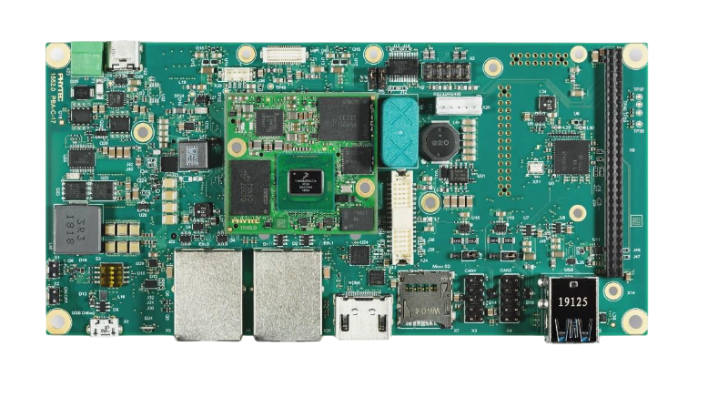
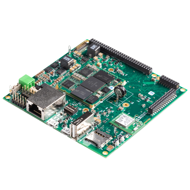
- The PhyBOARD Pollux from PHYTEC is a development board featuring an i.MX 8M Plus Quad with 4×1.6 GHz cores, a neural network accelerator, and connectivity options such as Ethernet w/ TSN, RS-232, RS-485, … which make it a good option for implementing process visualization applications, quality control, etc. (e03884af and documentation page).
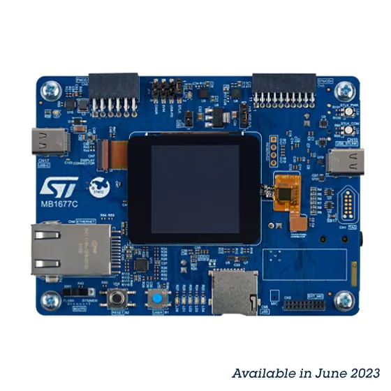
- STMicroelectronics keeps working on adding support for their STM32H5 boards, this week it’s the Nucleo H563ZI (784d7321).
- Power management support has been added for the Silicon Labs EFR32BG SoCs (c939d6a)
Drivers
- Really nice to see a new Ethernet controller driver for the popular LAN91C111 chip from SMSC/Microchip (28ff3e1d8c).
- The TI ADS7052 is a high-speed, low-power, 14-bit ADC with 1Msps throughput (9fa35bc9a0).
- The DS2482-800 from Analog Devices (Maxim) is a I²C to 1-Wire Bridge Device. It allows to talk to up to 8 1-Wire slaves from 1 I²C master. (691228ce01)
- A generic NTC (Negative Temperature Coefficient) Thermistor sensor driver has been added (5d4352f).
In order to make it more straightforward to convert raw resistance readings into actual temperature, a lookup table can be pre-generated using this script. Using the thermistor’s nominal resistance and its beta value (resistance value at 25°C / resistance value at 85°C), it spits out a lookup table in the form of a Devicetree node that the generic driver will then use to convert the measured resistance into an actual temperature.- You can check out the TDK RoboKit 1 board definition for an example of how the driver can be used/configured. See here for the thermistor sensor config, and here for its RT table.
- The SmartBond DA1469x SoC from Dialog (now Renesas) is a BLE-capable Cortex-M33 based chip, and Renesas just contributed an I2C controller driver for it: (6cf3fe1d3f).
- Support was added for the DDR memory controller on SiFive SoCs (71a6c22731)
- The Microchip MCP970x thermistors are low-cost, low-power sensors for measuring temperature in the -40°C to +125°C range. Thanks to Nick Ward, there’s now a driver for it in Zephyr! (162c47ffc4)
Bluetooth Audio Enhancements
- Several changes and refactoring around the Bluetooth LE Broadcast Audio functionality, in particular the implementation of the scan delegator. See PR #51679 for more details.
Noteworthy updates to existing drivers
- The driver for the popular BMI270 IMU (Inertial Motion Unit) now supports
ANY_MOTIONandDATA_READYinterrupts, making it possible to use the sensor in “trigger” mode vs. having to regularly poll data — quite convenient for actual motion detection, eh? (7d23e03) - NXP FlexCAN driver now supports CANFD variant (95b8bf3)
- Updated Microchip MEC172x QMSPI-LDMA driver to work with Zephyr’s SPI NOR flash driver. (5c00a83)
Samples
- The
die_temp_pollingsamples will now work out-of-the-box for all STM32 boards (and there are dozens!), as their Devicetrees have been updated with the relevant alias (die-temp0) for exposing the CPU Die temperature sensor (fee0c82). - Support for Scan Delegator added to Broadcast Audio Sink sample (e00500a)
- DHCPv4 sample now supports Arm FVP (Fixed Virtual Platform) (1ae558f5b4).
- The new IVSHMEM Doorbell Sample Application shows how two processes on different operating systems can communicate using ivshmem (Inter-VM Shared Memory Communication).
Housekeeping / API changes
- picolibc guru Keith Packard has proposed to change the
main()return type fromvoidtointin the entire code base. This better aligns with C and C++ standards. (see more details in PR #54628) - Removal of the need for a dummy device pointer in
SYS_INITfunctions (a5fd0d1).
As always please feel free to jump in with your thoughts or questions in the comments below, and we’ll talk next week!
Please also consider sharing the article in your professional network, as it makes a huge difference in getting these changes in front of the right people 🙂
If you enjoyed this article, don’t forget to subscribe to this blog to be notified of upcoming publications! And of course, you can also always find me on Twitter and Mastodon.