We’re only a week a way from the release of Zephyr 3.4, and everyone (including yours truly) is busy polishing everything for the release. I am trying to put together a nice video that will highlight some of the cool new features added in this version, even if you’ve already heard about some of them in the recent weeks if you’ve been reading this weekly update!
Since there isn’t much to cover in terms of actual Zephyr code changes (dozens of bugs have been fixed though, and commit activity has only barely slowed down), I am focusing this week’s article on 3 links you may have missed.
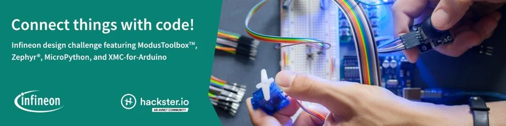
Infineon Hacking Challenge
Infineon just launched a coding challenge in partnership with Hackster.io around all things IoT and connected devices. The rules are super open and should leave you with room to create virtually anything you want! Bonus points if you’re using Zephyr, of course (to be clear: it’s not an official rule, just a personal recommendation 😊)!
You have until June 30 to submit your application and apply for getting some free hardware to help you with implementing your idea. You will then have until Sep. 22 to fully document your project and make your resource files (diagrams, BOM, code, etc.) available.
Adding PWM sound in Zephyr
Adding PWM sound in Zephyr – Blog post by Chris Gammell
Chris Gammell from Golioth recently published a nice and detailed article that dives into PWM (Pulse-Width Modulation) and how you can use it in Zephyr to dim LEDs—fun!—or even play sound—much funnier!
A reminder to fill out the Zephyr RTOS Technical Documentation Survey
A quick reminder that we have an ongoing documentation survey that should take you just 5 minutes to complete. The goal is to understand better how you (and your organization) are using the documentation today, and what are some of the things you’d potentially like to see improved.
Take the Zephyr RTOS Technical Documentation Survey
As always please feel free to jump in with your thoughts or questions in the comments below. See you next week!
If you enjoyed this article, don’t forget to subscribe to this blog to be notified of upcoming publications! And of course, you can also always find me on Twitter and Mastodon.
Catch up on all the editions of the Zephyr Weekly Update:
Like I mentioned last week, the release of Zephyr 3.4 is approaching (currently scheduled for June, 16), and the first release candidate is already out. There are slightly less noteworthy highlights this week, since last week’s post was published only a couple hours before the actual feature freeze deadline. So, since it should be a short read, I thought I would also take some time to list 3 things you can do to help make 3.4 a success!
This week in Zephyr land
Zephyr v2.7.5 LTS is out!
Chris Friedt from Meta, our release engineer for this LTS (Long-Term Support) version, just pushed the big button yesterday, and Zephyr v2.7.5 LTS is officially out the door. I will let you go through the release notes to catch up on the issues that have been addressed, but I would like to call your attention to the changes made around mbedTLS:
Moving mbedTLS to 2.28.x series (2.28.3 precisely). This is an LTS release that will be supported with bug fixes and security fixes until the end of 2024.
This version is incompatible with TF-M and because of this TF-M is no longer supported in Zephyr LTS. If TF-M is required it can be manually added back changing the mbedTLS revision on west.yaml to the previous one (5765cb7f75a9973ae9232d438e361a9d7bbc49e7). This should be carefully assessed by a security expert to ensure that the know vulnerabilities in that version don’t affect the product.
Notable changes in the 3.4 main branch
Like I said, this one will be short (or is it?), but some nice changes nevertheless. In a slightly less structured way as usual, here goes:
Testing
Pytest is a Python framework that “makes it easy to write small, readable tests, and can scale to support complex functional testing for applications and libraries”. A new plugin has been added for allowing to leverage Pytest in Twister test suites. This allows for more “advanced” tests that e.g. communicate with the flashed application on real or simulated hardware, which is accomplished through a device abstraction (concrete implementations are available for real-hardware over serial connection, qemu, an native POSIX). This opens the door to very advanced scenarios where e.g the device under test is running some kind of client application, and a test server can be started as a subprocess to test the entire client/server interaction. An example of a Pytest test that tests basic shell behavior can be found here, and there are some pull requests opened that demonstrate even more complex scenarios. See more in the documentation here (PR #57117).
Robot Framework, a generic open source automation framework, is now also supported as a test harness! This makes it very easy to run tests on top of the Renode emulation/simulation framework. I really like how the Robot Framework makes test super easy to read for a human. See for yourself, with the test below that checks if the version shell command works as expected. More info about this feature in the documentation page here (PR #56770).
Should Read Version From Shell
    Prepare Machine
    Start Emulation
    Wait For Prompt On Uart   uart:~$
    Write Line To Uart        version
    Wait For Line On Uart     Zephyr version
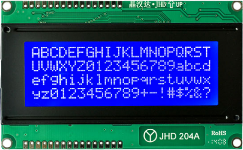
Auxiliary Displays are text-based displays that have simple interfaces for displaying textual, numeric or alphanumeric data […] auxiliary displays do not support custom graphical output to displays (and and most often monochrome), the most advanced custom feature supported is generation of custom characters. These inexpensive displays are commonly found with various configurations and sizes, a common display size is 16 characters by 2 lines.
As always, a good way to get started with this new functionality is to check out to the dedicated code sample. You will certainly note that the API couldn’t be more straightforward!
snprintk(data, sizeof(data), "Hello world from %s", CONFIG_BOARD);
rc = auxdisplay_write(dev, data, strlen(data));
Performance improvements for LVGL. The various performance tuning settings added by Daniel DeGrasse allow speed improvements up to 10x (from 3fps to 34!) on e.g. i.MX RT1170 👏 (PR #39 in Zephyr’s LVGL fork, and PR #57421).
Sensors
A new asynchronous way to interact with sensors has been introduced: raw sensor data can be acquired asynchronously using RTIO, and processed by an application-controlled thread via the decoder API. A very detailed section has been added to the documentation here, and the Sensor shell example module has been updated to use this new mechanism, so don’t hesitate to refer to it (PR #57962).
New command in the Sensor shell module: sensor trig. This command helps understand the trigger mechanism. It allows to enable/disable triggers directly from the shell and, as soon as a trigger (only data_ready supported for now) happens, a moving average for the different channels gets updated, and is output to the console when SENSOR_SHELL_TRIG_PRINT_TIMEOUT_MS milliseconds have elapsed (PR #58257).
Drivers
Added board Pin controller for the Pmod and Arduino shield interface of the Synopsys ARC EMSDP (PR #56926).
New Ethernet driver for Analog Devices ADIN2111. The ADIN2111 is a low power, 2-port 10BASE-T1L transceiver designed for industrial Ethernet applications, and is compliant with the IEEE® 802.3cg-2019™ Ethernet standard for long reach, 10 Mbps single pair Ethernet (SPE). (PR #57848).
USB Full-Speed is now supported for the USB device controller on NXP LPC55S36 and LPC55S59 (PR #58095).
Miscellaneous
New asynchronous CoAP client, supporting plain UDP sockets as well as DTLS. Check out the dedicated documentation page for more information (PR #56970).
TF-MPSA (TrustedFirmware-M Platform Security Architecture) APIs usability improvements that bring more flexibility in the way to build and link the various mbedTLS library into secure and non-secure applications (PR #58023). See a very complete and well-documented code sample here.
A first-time contribution by @tkng-rivos added support for OpenTitan watchdog (PR #57501). As a reminder, OpenTitan is an open-source reference design for silicon root of trust (RoT) chips.
Help with 3.4 release
Test, test, test!
Please take 3.4 RC1 for a spin! In particular, if you already plan on moving your product development to 3.4, then now is the perfect time to start doing so. All features are essentially in, and the RC1 is essentially very similar to what the final release will be, minus perhaps some outstanding bugs or regressions that you can contribute to help catching. Please report any issue directly in the project’s GitHub issue tracker.
Review the documentation
This one can be particularly interesting if you’ve never actually contributed back to Zephyr, and were maybe scared of doing so for you never had any code to contribute. I cannot stress enough that contributing to improving the documentation (including trivial fixes such as correcting typos!), is immensely valuable too, and not every contribution has to be code!
If you end up giving some of the new (or older) features a try, make sure to send pull requests should you catch mistakes in the documentation, things that could be explained better, etc.
On that note, we have an ongoing documentation survey that should take you just 5 minutes to complete. The goal is to understand better how you (and your organization) are using the documentation today, and what are some of the things you’d potentially like to see improved.
Take the Zephyr RTOS Technical Documentation Survey
Help spread the word
Whether you’re directly involved with the project as a contributor or maintainer, or whether you’re just a user, I would really encourage you to think about what you could do to help spread the word when the release will come out.
One thing that I would really love to see is cool demos of Zephyr 3.4 in action. So, for example, if you’ve been helping get a new board added (dozens were contributed since 3.3!) in 3.4, why not work on a short video that would showcase Zephyr running on it? Bonus points if it also showcases some of the recently added features, of course 🙂 If this sounds like something that you would like to do, please feel free to ping me if you have some ideas or questions!
A big thank you to the 4 individuals who had their first pull request accepted this week 💙 🙌: Andrei, Göran, Kornel, and Tyler.
As always please feel free to jump in with your thoughts or questions in the comments below. See you next week!
If you enjoyed this article, don’t forget to subscribe to this blog to be notified of upcoming publications! And of course, you can also always find me on Twitter and Mastodon.
Catch up on all the editions of the Zephyr Weekly Update:
Today is the last day for new features to get merged into the main Zephyr repository, as the next few weeks will be dedicated to documenting, testing, and polishing the upcoming 3.4 release.
Before diving into this week’s noteworthy updates, and since I know many of you are actually building products based on Zephyr, I wanted to remind you about Zephyr’s Vulnerability Alert Registry.
If you are building a product on Zephyr—and I know many of you are!—you probably want to know ahead of time should a security vulnerability impact you and your customers, so that you can properly address it. I would really encourage you to review the criteria for participation and apply, it should take you literally 30 seconds of your time.
And now for this week’s update 🙂
Bluetooth Telephony and Media Audio Profile
Bluetooth is an incredibly active space, and there are just so many profiles one can chose from to build a standard-based wireless solution. And of course, Bluetooth is particularly popular for all things telephony, so it’s great to see that initial support for Bluetooth LE Telephony and Media Audio Profile (TMAP) was added this week (#56686).
The Telephony and Media Audio Profile (TMAP) establishes configuration settings of underlying audio-related specifications to allow manufacturers to deliver interoperable conversational, streaming, and broadcast audio user experiences in a wide variety of telephony and media products. This includes products such as headsets, TVs, smartphones, personal computers, headphones, earbuds, wireless speakers, and wireless microphones.
Two samples have been added: tmap_central mimics a smartphone while tmap_peripheral reflects an earbud that would act as a Call Terminal, with audio being streamed from the “smartphone” upon connection.
Huge kudos to Silviu Petria from NXP, as this is their first contribution to Zephyr, and a pretty significant one!
MCUboot on ESP32
When using Zephyr on ESP32, one would have historically relied on the ESP-IDF bootloader as the second-stage bootloader. The typical application startup flow is actually very well described in the ESP-IDF documentation.
With the merge of pull request #54835, MCUboot bootloader can now be used instead, and developers can handle firmware signing, over-the-air updates, etc. in a familiar manner.
Read more in the documentation of each ESP32 supported board.
New memory barrier API
A new API has been introduced for data memory barriers. Data barriers are essentially a way to nicely tell your processor: : “Hey, I know you like to rearrange tasks for efficiency, but these particular memory operations need to happen in the exact order I’ve given them! 😘“. This is particularly useful in Symmetric Multi-Processing (SMP) scenarios, but can also be needed in multi-threaded applications or when hardware is accessed asynchronously.
The new barrier API enables a more consistent way to implement synchronization fences, regardless of the processor architecture. (#57439)
GoogleTest (a.k.a gTest), is a unit testing library developed by Google. It is used for writing test cases in C++ and supporting test-driven development. It provides a rich set of assertions, automatic discovery of tests, and a human-readable test output format.
Thanks to Yuval’s contribution in PR #58046, Twister now supports using GoogleTest as a harness for your tests, bringing you an alternative to ztest, pytest, etc..
Boards, shields & SoCs
This been has been pretty busy on this front as a few boards were added. What’s more, I always find it nice when existing boards and SoCs get even fuller support for Zephyr (see Xtensa MMU work below).
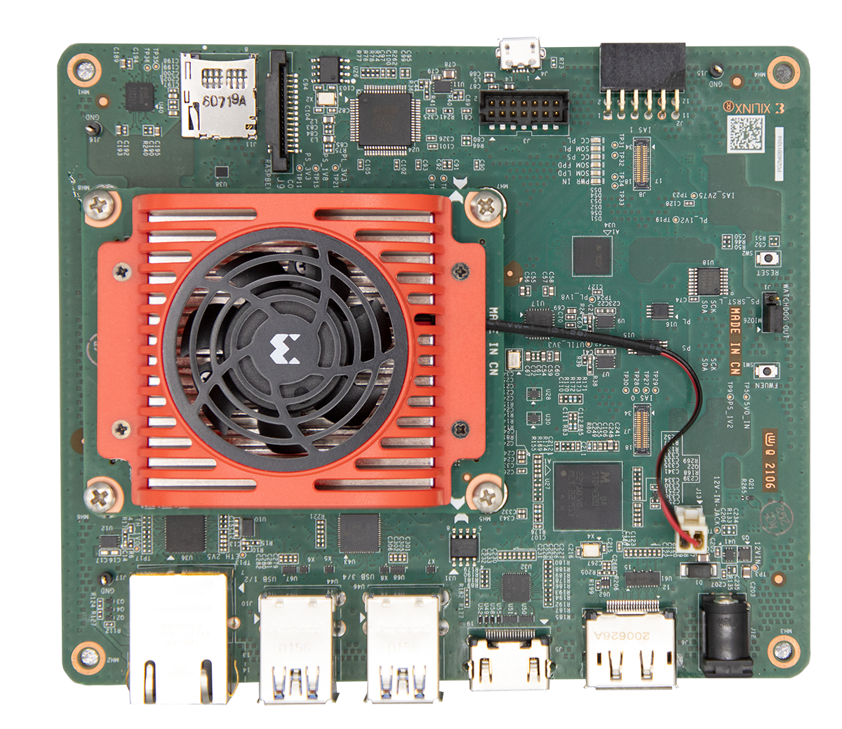
The Kria KV260 AI Starter kit from Xilinx is a devkit for the Kria K26 SOMs that targets avanced edge computer vision scenarios. It includes a real-time processing unit (RPU) based on a dual-core Cortex-R5F, and #54916 introduces support for it. Head over to the dedicated documentation page for more info.
Initial support for Xtensa MMU version 3 has been added (#57908) and can be enabled through the XTENSA_MMU KConfig flag.
A CAN driver for Microchip SAMC21 has been added (#50408)
An update has been made to the Panasonic Grid-EYE shield, which is an evaluation shield for the AMG8833 8×8 pixel thermal camera. Read more here (#53244)
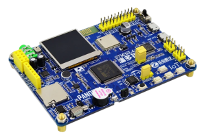
STM32L475 Pandora board
The STM32L475 Pandora board from Alientek is now supported thanks to @QinYUN575‘s first contribution to the project 🙂 (#55577)
New drivers
A nice addition to the SPI driver is that it now allows collecting statistics (number of bytes transmitted/received, # of transfer errors, …). This feature can be enabled using the SPI_STATS KConfig option. (#57767)
Fuel gauges:
Fuel gauge driver API now includes support for relative-state-of-charge and absolute-state-of-charge (existing drivers for MAX17048 and generic SBS have been updated to reflect the change). (#57824)
SBS fuel gauges expose informations such as chemistry, manufacturer name, device name, … through buffer registers. They can now be accessed through the newly introduced fuel_gauge_get_buffer_property API (#58014).
Shout out to Microsoft for the great contributions in this area!
The ADP5360 from Analog Devices is a one-stop shop battery management PMIC with ultra-low power fuel gauge, battery protection, buck regulator, and more. The initial version of the driver that got added this week adds support for the buck/buck boost part of this IC. (#58184)
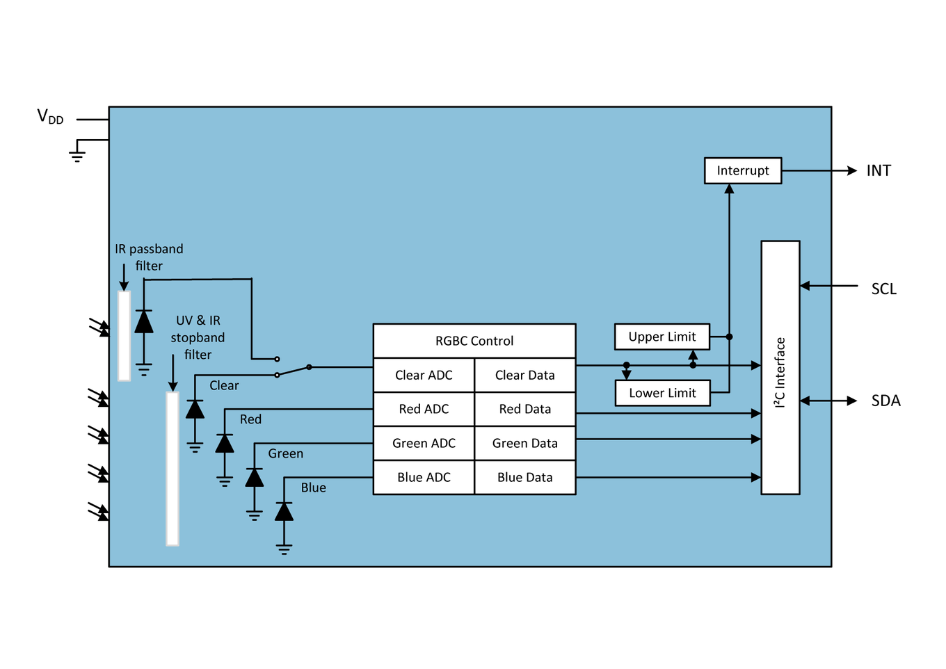
TSC 3400 diagram
A new driver is available for the TSC3400 color sensor. An interesting feature of this sensor is that it actually includes 5 channels. Beyond red, green, and blue, you also get a “Clear” channel for measuring overall luminosity, and “Infrared” which can be used for measuring color temperature. (#58144)
I’ve had my eyes on recently merged pull request #48389 for a long time, as it adds support for the Microchip MCP9600 thermocouple amplifier. It supports most types of thermocouples, meaning that you can aim for as cold as -200℃ or as hot as 1,800℃! As I plan on building a Zephyr-based temperature monitor for my raku pottery kiln, I am really happy to see this driver merged in the official repo!
A new driver is available for ARC DesignWare Data Fusion Subsystem SPI (#56925)
ADC driver has been added for Renesas Smartbond. Both GPADC (10-bit resolution by default) and SDADC (14-bit) are supported. (#57164)
Added USB interface driver for the Renesas Smartbond DA1469x device family. (#56977)
An initial version of a driver for Infineon CAT1 watchdog has been added (#57910)
Miscellaneous
You can now enable or disable the shell prompt using the shell prompt [on|off] command. (#57736)
As always please feel free to jump in with your thoughts or questions in the comments below. See you next week!
If you enjoyed this article, don’t forget to subscribe to this blog to be notified of upcoming publications! And of course, you can also always find me on Twitter and Mastodon.
Catch up on all the editions of the Zephyr Weekly Update: